Choosing the right Pneumatic Ball Valve is more than selecting a valve size and actuator. The correct choice protects process stability, worker safety, and long-term equipment performance. In real facilities, a valve may handle clean water, abrasive slurry, corrosive chemicals, or compressed air. Each service demands a different combination of body material, seal design, port size, and pressure rating.
Start with the process. Identify the medium, operating temperature, working pressure, flow rate, and required shutoff performance. Then compare these conditions with verified manufacturer datasheets and applicable industry standards. Stainless steel may suit corrosive environments, while reinforced polymer seats can perform well in selected chemical applications. However, material compatibility should never rely on assumptions. A seal that performs perfectly in water may swell or crack in oil.
Actuator selection also deserves careful attention. Calculate the valve’s breakaway and running torque, then allow a sensible safety margin. Undersized actuators can stall during startup. Oversized actuators may increase cost and mechanical stress. Choose double-acting operation for straightforward control, or spring-return operation when the valve must move to a defined safe position after air loss. Clean, dry instrument air is essential, although this detail is often neglected.
Experienced technicians also inspect mounting standards, cycling frequency, accessories, and maintenance access before installation. A cheaper Pneumatic Ball Valve may become expensive after repeated seal failures or difficult repairs. Small details matter. This guide examines the practical decisions behind reliable selection, while acknowledging that no single valve suits every application. Careful verification remains the most dependable approach.
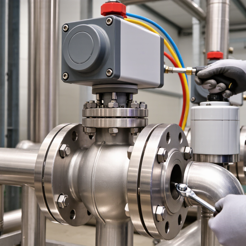
Choosing a pneumatic ball valve starts with understanding its internal movement. A quarter-turn actuator rotates a drilled ball inside the valve body. When the bore aligns with the pipe, fluid passes with low resistance. A 90-degree turn closes the passage. Simple, but not always forgiving.
Pneumatic actuators generally use compressed air to create rotary torque. Double-acting models use air for both opening and closing. Single-acting models use air in one direction and a spring in the other. This spring-return action can move the valve to a safer position after air loss, depending on the installation. In practice, I check the required failure position before comparing prices. That step is often missed.
Valve types differ in body design, port pattern, and sealing materials. Two-way valves control one flow path; three-way valves divert or mix flow. Full-port designs provide a bore close to the pipe diameter. Reduced-port designs are often smaller and less expensive, but they can increase velocity and pressure loss. Seat material must match temperature, pressure, and chemical compatibility. Metal seats tolerate harsher service, while softer seats may seal better at moderate conditions. I would not trust a catalog number alone. Confirm torque, air pressure, cycle frequency, connection size, and tested leakage limits with the supplier. A small mismatch can cause slow movement, noisy operation, or premature seat wear.
How to Choose the Right Pneumatic Ball Valve?
The fluid decides the valve body, ball, seat, and stem seals. For clean water, stainless steel offers strong corrosion resistance and easy maintenance. Brass can work well in moderate service, but chloride-rich water deserves caution. Plastic bodies may suit mild chemicals, yet ultraviolet exposure and temperature can reduce their service life. Always check the chemical compatibility chart at the actual concentration.
Pressure and temperature must be evaluated together. A valve marked PN16 does not guarantee 16 bar at every temperature. Steam is a useful warning. NIST Chemistry WebBook data shows saturated water vapor reaches about 4.76 bar absolute at 150°C. The valve, seat, and seal must tolerate that condition continuously. PTFE seats resist many chemicals, but high heat, cycling, and permeation may change performance. Elastomer seals need equal attention. Small differences in compound selection can create large leakage problems.
The pneumatic actuator also needs realistic air-demand calculations. The U.S. Department of Energy’s Improving Compressed Air System Performance sourcebook reports that leaks can waste 20–30% of compressor output. A poorly sized actuator can add avoidable losses. In commissioning work, catalog ratings sometimes look reassuring, but the operating details are incomplete. Check pressure surges, cycling frequency, fluid cleanliness, and installation orientation. A neat selection table can still mislead. Recheck every assumption before ordering.
Matching Valve Materials to Fluid, Pressure, and Temperature Requirements
PVC and polypropylene are suitable for many water-based and mildly corrosive fluids. PTFE is preferred for aggressive chemicals, while stainless steel is widely used for clean, hot, or mechanically demanding fluids.
Select a valve whose pressure rating exceeds the maximum operating pressure, including surges. Typical thermoplastic ball valves are often rated around 10 bar at room temperature, while metal valves may support higher ratings depending on design.
The chart shows typical upper continuous temperature limits for common body materials. Pressure ratings usually decrease as temperature rises, so always verify the manufacturer’s pressure-temperature curve.
Typical engineering reference values; actual limits depend on valve design, seals, pressure class, fluid composition, and operating conditions.
How to Choose the Right Pneumatic Ball Valve?
Port size should match the pipeline, not merely the equipment connection. A smaller port can restrict flow and create pressure loss. An oversized valve may increase cost and reduce control accuracy. Check the required flow rate, pressure drop, media temperature, and viscosity. For compressed-air systems, the U.S. Department of Energy reports that leaks can waste 20–30% of compressor output. Therefore, poor sizing can increase energy loss and operating costs.
Connection selection also matters. Threaded ends suit compact, low-maintenance installations. Flanged connections provide stronger support for larger valves and frequent servicing. Confirm the standard, nominal size, pressure class, and face-to-face dimension before ordering. ISO 5211 specifies actuator mounting interfaces, but it does not guarantee correct torque. Valve friction, line pressure, and safety factors still require calculation. Field conditions are rarely perfect. A clean specification can still fail when moisture, rust, or dirty air enters the actuator.
Tips: Select the actuator after confirming valve torque. Use a safety margin, but avoid excessive oversizing. The actuator should overcome breakaway torque, running torque, and emergency conditions. A filter-regulator-lubricator unit can improve reliability, although lubrication requirements vary. Review actual plant data, not only catalog values. This step is often skipped. It should not be.
| Selection Area | Option / Size | Technical Data | Recommended Use | Important Selection Check |
|---|---|---|---|---|
| Port Size | DN15 / NPS 1/2 | Nominal bore: 15 mm; compact line size | Instrument air, water, small utility lines, and compact automation systems | Confirm the valve flow coefficient (Cv/Kv), tubing size, and allowable pressure drop |
| DN20 / NPS 3/4 | Nominal bore: 20 mm; frequently used utility size | General industrial air, water, and low-viscosity fluid service | Avoid selecting by pipe diameter alone; check actual required flow rate | |
| DN25 / NPS 1 | Nominal bore: 25 mm; common process and utility size | Compressed air, water, oil, and compatible process fluids | A full-port design generally provides lower restriction than a reduced-port design | |
| DN40 / NPS 1-1/2 | Nominal bore: 40 mm; medium flow capacity | Process skids, water distribution, and larger pneumatic utility lines | Check actuator output torque at the lowest available air pressure | |
| DN50 / NPS 2 | Nominal bore: 50 mm; standard process-line size | Industrial water, air, gas, and compatible liquid services | Verify pressure class, end-to-end dimensions, and available installation space | |
| DN80–DN100 / NPS 3–4 | Nominal bore: 80–100 mm; higher flow capacity | Main utility headers, water systems, and larger process lines | Consider piping support, actuator weight, operating torque, and emergency shutdown requirements | |
| Port Design | Full Port | Ball bore is approximately equal to the connected pipe bore | Systems requiring low pressure loss, pigging, draining, or high flow capacity | Usually larger, heavier, and more expensive than reduced-port designs |
| Reduced Port | Ball bore is smaller than the nominal pipe size | General on/off isolation where moderate pressure loss is acceptable | Use the manufacturer’s Cv/Kv data to confirm flow performance | |
| Two-Way, 2/2 | Two ports; straight-through isolation service | Most common configuration for opening and closing a flow path | Confirm the valve is rated for the fluid, temperature, and pressure | |
| Three-Way, L-Port | L-shaped internal passage; switching or diverting service | Routing one inlet to one of two outlets | Check the required flow pattern at every actuator position | |
| Three-Way, T-Port | T-shaped internal passage; mixing or multiple routing paths | Mixing two inlets or distributing flow to multiple outlets | Do not assume all port positions provide shutoff; review the flow diagram | |
| Connection Type | NPT Threaded | Tapered pipe thread commonly specified to ASME B1.20.1 | Compact installations and North American threaded piping systems | NPT is not interchangeable with BSP threads; use compatible fittings and sealants |
| BSPP Threaded | Parallel pipe thread generally specified to ISO 228-1 | Installations using parallel threaded connections and sealing washers or gaskets | Confirm the sealing method because the thread itself is not tapered | |
| BSPT Threaded | Tapered pipe thread generally specified to ISO 7-1 | Threaded piping systems using tapered BSP connections | Do not mix BSPT and NPT without a properly rated adapter | |
| Flanged | Flange drilling may follow ASME B16.5, EN 1092-1, or another specified standard | Large lines, frequent maintenance, and higher mechanical loads | Match nominal size, pressure class or PN rating, facing type, bolt pattern, and gasket | |
| Tri-Clamp / Sanitary | Clamp connection with hygienic surfaces; dimensions may follow ISO 2852 or ASME BPE practices | Food, beverage, pharmaceutical, and clean-process applications | Specify surface finish, elastomer compatibility, cleanability, and hygienic certification | |
| Actuator Configuration | Double-Acting Pneumatic | Compressed air is supplied for both opening and closing | Applications requiring controlled cycling and no defined position on air failure | Requires a reliable air supply or a separate emergency positioning system |
| Spring-Return, Fail Close | Air opens the valve; springs close it when air is removed | Fuel, gas, chemical, or process isolation where closing is the safer failure position | Size the actuator for required closing torque at minimum air pressure and maximum valve torque | |
| Spring-Return, Fail Open | Air closes the valve; springs open it when air is removed | Cooling, purge, bypass, or other services requiring flow during air failure | Confirm that the process is safe with the valve in the open position | |
| Modulating Pneumatic | Uses a positioner and control signal for intermediate valve positions | Flow, pressure, temperature, or level control where throttling is permitted | Verify that the ball valve design, positioner, and control signal support continuous modulation | |
| Actuator and Accessory Checks | Operating Torque | Actuator output must exceed the valve’s breakaway, running, and seating torque requirements | All automated ball-valve installations | Use valve-specific torque data; account for pressure, temperature, fluid, seat material, and safety margin |
| Air Supply | Common actuator supply ranges include approximately 4–8 bar(g), subject to the actuator specification | Industrial compressed-air systems | Select the actuator using the lowest actual supply pressure, not the compressor’s maximum pressure | |
| Mounting Interface | ISO 5211 mounting patterns are commonly used for quarter-turn valve actuators | Direct mounting of pneumatic actuators to automated ball valves | Match flange pattern, drive-square dimensions, stem height, and rotation direction | |
| Accessories | Solenoid valve, limit switch box, position indicator, filter-regulator, speed controller, or positioner | Automation, remote monitoring, emergency shutdown, and process control | Confirm voltage, protection rating, signal type, air quality, response time, and required certification | |
| Final Application Review | Pressure and Temperature | Valve rating is determined by body, seat, seal, connection, and temperature limitations | Every fluid and gas application | Compare the complete pressure-temperature rating with the maximum operating conditions |
| Material Compatibility | Common body materials include brass, stainless steel, and carbon steel; seats and seals vary by service | Water, air, oil, chemicals, gases, and hygienic fluids | Check chemical compatibility, corrosion resistance, permeability, and temperature range | |
| Installation and Maintenance | Allow access for actuator removal, seal replacement, inspection, and manual override | New installations and replacement projects | Confirm flow direction, valve orientation, cycle frequency, spare parts, and local safety requirements |
Note: Port sizes, pressure ratings, flow coefficients, torque values, materials, and temperature limits vary by valve design. Final selection should be verified against the applicable technical datasheet and site operating conditions.
Choosing a pneumatic ball valve starts with its control behavior, not its pipe size. Define the required torque, cycle rate, response time, and failure position. Spring-return actuators usually provide a clearer fail-safe response than double-acting units. Add position feedback when operators need proof of open or closed status. A manual override can help during commissioning, but it may introduce unsafe bypass habits.
Safety depends on the complete assembly. Check the valve, actuator, solenoid, fittings, and control signals together. ISO 4414 addresses safety requirements for pneumatic systems, while ISO 5211 helps confirm actuator-to-valve mounting compatibility. The U.S. Department of Energy’s Improving Compressed Air System Performance sourcebook estimates that leaks can waste 20–30% of compressor output. That makes air-quality control practical, not cosmetic. Use filtration and drainage that match ISO 8573-1 requirements. Moisture inside a cold plant room can quietly damage performance.
Maintenance should be visible and measurable. Inspect the air filter, tubing, exhaust muffler, and actuator seals at planned intervals. Record cycle counts and closing time. A sticky valve often gives warning before failure. In dusty service, inspect the stem area by hand, not only through software. The perfect specification is rare. I would rather select a modest valve with accessible spares than an advanced unit nobody can service. Overlooking local condensate is still an easy mistake.
How to Choose the Right Pneumatic Ball Valve?
Comparing Performance, Installation Conditions, and Total Operating Costs
Choosing a pneumatic ball valve is not only a pressure-rating exercise. In field inspections, I compare operating performance with the installation environment and lifetime cost. Start with the fluid, temperature, pressure, flow rate, and required shutoff class. Valve size should follow actual flow demand, not simply the existing pipe diameter. A poorly sized valve can cause pressure loss or unstable control. Check torque requirements across the full pressure range. Pneumatic actuator output must exceed breakaway torque with a practical safety margin. Keep it measurable.
Installation conditions often decide whether a good valve performs well. Pipework should be aligned, supported, and free from external loading. Even a small offset can stress the body and shorten seal life. Confirm actuator clearance before fitting insulation or nearby instruments. Wet or dusty areas may require suitable protection for air accessories and position feedback. Clean, dry instrument air matters. Drain the filter regularly. I have seen commissioning delays caused by overlooked tubing connections, not valve defects. That lesson is easy to miss.
Total operating cost includes more than purchase price. Compare air consumption per cycle, expected cycling frequency, seal replacement intervals, inspection labor, and downtime risk. A fast actuator may improve productivity, yet waste air if control settings are excessive. Solenoid failures and leaking fittings can quietly raise compressor demand. Include spare parts and access time in the calculation. Also verify the fail-safe position required by the process. A cheaper valve may fit today but create expensive maintenance later. The estimate will never be perfect. Review it after real operating data arrives.
Fluid chemistry guides the body, ball, seat, and seal materials. Clean water often suits stainless steel. Brass may work in moderate service. Chloride-rich water needs caution. Check compatibility at the actual concentration, not a guessed value.
They may suit mild chemicals and lower temperatures. Ultraviolet exposure can weaken plastic over time. Heat may shorten its service life. The choice is not automatic.
No. Pressure ratings can change with temperature. At 150°C, saturated water vapor reaches about 4.76 bar absolute. The valve, seat, and seals must tolerate continuous exposure. Temperature changes the real pressure limit.
PTFE seats resist many chemicals, but heat and repeated cycling can change performance. Permeation may also affect sealing. Elastomer compounds require equal attention. Small material differences can cause major leakage.
Match the port to the pipeline and required flow. A smaller port can restrict flow and increase pressure loss. An oversized valve may cost more and control poorly. Check flow rate, viscosity, temperature, and pressure drop.
Threaded ends suit compact installations with limited maintenance needs. Flanged connections provide stronger support for larger valves. They also help during frequent servicing. Confirm size, pressure class, connection standard, and face-to-face dimension.
Select the actuator after confirming valve torque. It must overcome breakaway torque, running torque, and emergency loads. Add a sensible safety margin. Excessive oversizing wastes resources. Catalog ratings can look reassuring. They may still be incomplete.
Check pressure surges, cycling frequency, fluid cleanliness, and installation orientation. Also review moisture, rust, and dirty instrument air. A filter-regulator-lubricator unit may improve reliability. Lubrication requirements vary, so confirm them carefully. This step is often skipped. That deserves a second look.
Choosing the right Pneumatic Ball Valve requires more than selecting a suitable size. Start by understanding the valve’s operating principle and available designs, such as two-way or three-way configurations, single-acting or double-acting actuators, and full-port or reduced-port options. The valve material should match the fluid being controlled, while its pressure and temperature ratings must safely handle actual operating conditions. Consider the correct port size, connection type, and actuator arrangement to ensure reliable installation and efficient flow control.
A complete evaluation should also include control features, response requirements, safety provisions, and maintenance accessibility. Factors such as installation environment, operating frequency, sealing performance, air consumption, service life, and replacement costs can significantly affect long-term value. By comparing performance, compatibility, installation conditions, and total operating expenses, users can select a Pneumatic Ball Valve that delivers dependable control, safe operation, and efficient maintenance throughout its service life.

KR VAVLE