Why Choose a Motorized Ball Valve for Your Application?

Time:2026-09-14 Author:Madeline
0%

Choosing a Motorized Ball Valve is not simply a matter of adding an actuator to a pipeline. It is a decision about control, reliability, energy use, and future maintenance. In a chilled-water line, for example, a valve may open hundreds of times each day while responding to temperature changes. Its torque, flow coefficient, enclosure rating, and cycle life must match those conditions.

Valve-automation specialist Michael R. Miller offers a practical reminder: “The best valve is not the fastest one; it is the one that delivers repeatable control with the lowest practical risk.” That principle explains why Motorized Ball Valve selection deserves careful engineering. A compact brass valve may suit clean water, yet fail prematurely in a corrosive process. A stainless-steel body, suitable seal material, and correctly sized actuator can make a major difference.

Small details matter.

The control signal must also match the building management system or PLC. Two-way and three-way configurations serve different flow paths. Fail-open or fail-closed operation can affect safety and equipment protection. Manual override is valuable when power disappears unexpectedly. Still, specifications alone do not guarantee success. Installation quality, wiring, condensation, and infrequent exercising can create problems that appear unrelated to the valve.

That assumption can be wrong.

This guide examines why engineers choose a Motorized Ball Valve, where its advantages are strongest, and which limitations deserve honest attention. The goal is not to promote one product blindly. It is to help readers compare real operating conditions with realistic valve performance.
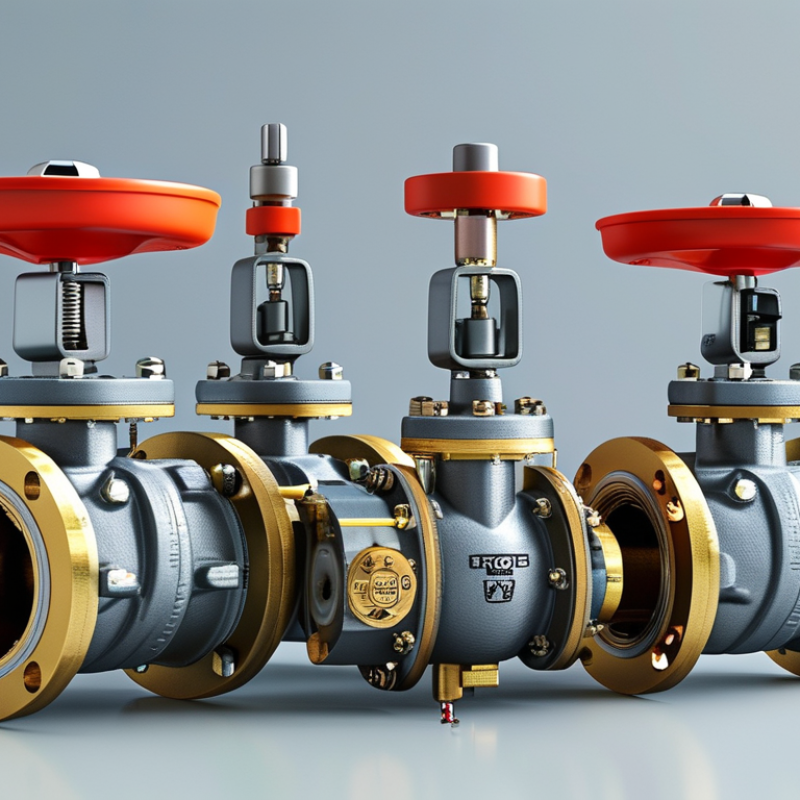
Why Choose a Motorized Ball Valve for Your Application?

What Is a Motorized Ball Valve? Full-Bore Design and 90° Actuation

A motorized ball valve uses an electric actuator to rotate a drilled ball inside the valve body. Its 90° actuation moves the valve from fully open to fully closed with a quarter turn. This motion is simple, fast, and easy to control through switches, relays, or automated systems. The full-bore design keeps the internal passage close to the connected pipe diameter. That reduces pressure loss and helps liquids, gases, and clean process media flow with fewer restrictions.

In practical installations, I look closely at pipe size, operating pressure, temperature, and actuator torque. A full-bore valve can be useful where steady flow matters, such as water lines, cooling circuits, and process equipment. The actuator also supports repeatable operation, especially when manual access is limited. It can open or close at a defined time. That matters.

However, motorized control is not automatically the best choice. A poorly sized actuator may stall, overheat, or close too slowly for the system. I have also seen installers overlook condensation around electrical connections. That small detail can create unreliable signals later. Check the valve material, sealing method, enclosure rating, and required fail position before installation. A 90° movement sounds straightforward, but control timing and emergency response still need careful testing. Sometimes, a manual override is worth including. Not always.

How Do Electric Actuators Work? Typical 5–30-Second Valve Cycle Times

Why Choose a Motorized Ball Valve for Your Application?

An electric actuator converts motor rotation into controlled valve movement. A small motor drives a gear train, which turns the ball through 90 degrees. Limit switches stop the motor at fully open or closed positions. Many compact assemblies complete this cycle in 5–30 seconds. The exact time depends on torque, gear reduction, valve size, and supply voltage.

According to the International Energy Agency, electric motors consume about 45% of global electricity. The U.S. Department of Energy also reports that motor-driven systems use roughly 69% of industrial electricity. These figures make actuator efficiency more than a minor design detail. A correctly sized actuator avoids unnecessary power draw and reduces mechanical stress. It also provides repeatable positioning in water treatment, process piping, and building services.

Cycle time needs careful interpretation. A 10-second specification may describe only the rotation, not signal delay or system response. During commissioning, engineers should check actual travel time under load. A stiff valve can slow movement. Poor voltage can cause overheating. This part is sometimes overlooked. A slower 30-second cycle may protect piping from pressure shock better than a fast movement. However, emergency isolation may require a shorter response. Select the actuator after reviewing torque, duty cycle, fail-position requirements, and control feedback—not from cycle time alone. Industry guidance from IEC 60534-4 supports testing valve response and leakage under defined operating conditions.

Why Choose a Motorized Ball Valve?

Electric actuators convert motor rotation into quarter-turn valve movement through a gear mechanism. The chart shows representative full-cycle times for common application categories within the typical 5–30-second range. Actual performance depends on valve size, torque, supply voltage, and load.

A motorized ball valve is suitable when repeatable positioning, remote control, and automated shutoff are required. The actuator receives an electrical signal, drives the valve approximately 90 degrees, and stops when the open or closed limit is reached.

Which Applications Benefit Most? Flow Control from DN15 to DN300

Motorized ball valves are useful when an application needs dependable flow control without constant manual adjustment. The strongest benefits appear across DN15 to DN300, where pipe size, pressure, and operating frequency can vary considerably. Small DN15 lines often serve water treatment skids, heating circuits, and compressed-air equipment. Their compact design fits crowded panels and service areas.

Medium sizes, such as DN25 to DN100, suit building services, irrigation zones, process cooling, and tank filling systems. An electric actuator can open or close the valve on a timed signal, sensor input, or control system command. This reduces repeated manual work and helps maintain consistent flow.

However, actuator torque must match the valve’s pressure and media conditions. A quick selection based only on pipe diameter can fail.

Larger DN150 to DN300 valves commonly support chilled-water networks, industrial cooling, fire-water testing systems, and large process lines. Here, slow operation can reduce water hammer compared with sudden manual movement. The valve material must also suit the fluid, temperature, and corrosion risk. Clean water is simple. Chemical service is not.

Installation details matter. Allow space for actuator removal, protect electrical connections from moisture, and confirm the required control signal before commissioning. A normally open or normally closed position may affect safety and maintenance procedures. Oversizing is another common mistake. It may increase cost and reduce control accuracy, especially where the flow demand changes frequently.

How Do Pressure, Temperature, and IP65 Ratings Affect Valve Selection?

A motorized ball valve can simplify remote flow control, but its ratings must match the installation. Pressure is not only a pipe-size concern. Check the working pressure, pressure differential, and fluid type before selecting the actuator. A valve may handle high static pressure yet struggle when flow creates heavy torque. That mismatch can cause slow movement, overheating, or premature gear wear. Select a suitable torque margin, not the smallest available actuator.

Temperature affects both the valve body and electrical actuator. Hot water, steam, and outdoor heat can reduce seal life and damage internal components. Confirm the media temperature and surrounding air temperature separately. These values are often different. A cold outdoor night can also affect grease and response time. Field reviews commonly find that designers check peak temperature but overlook continuous exposure. That shortcut needs reconsideration.

An IP65 enclosure is dust-tight and resists water jets from any direction. It is not designed for immersion. A washdown area may meet IP65 conditions, but standing water can still enter through cable glands or damaged seals. Use correctly rated cable entries and mount the actuator away from direct spray when possible. Test the complete installation, not just the valve housing. Small details matter. A motorized valve is reliable only when pressure, temperature, wiring, and enclosure protection are evaluated together.

What Are the Lifecycle Benefits? Up to 100,000 Rated Operating Cycles

Why Choose a Motorized Ball Valve for Your Application?

What Are the Lifecycle Benefits? Up to 100,000 Rated Operating Cycles

A motorized ball valve can deliver controlled flow without repeated manual turning. Its rated life may reach 100,000 operating cycles under specified conditions. That matters in water treatment, HVAC, process lines, and hard-to-access pipework. Less manual handling can reduce labor exposure and improve repeatability. Real plants are messier, though. Poor sizing, abrasive media, voltage instability, or frequent water hammer can shorten service life.

The U.S. Department of Energy’s Industrial Motor Systems Market Assessment reports that motor-driven systems use about 69% of industrial electricity. This highlights the value of efficient actuation, even when a valve motor runs only briefly. NIST Handbook 135 also identifies energy, maintenance, replacement, and disposal as lifecycle-cost factors. A properly selected valve can reduce inspection visits and unexpected stoppages. Still, a 100,000-cycle rating is not a universal promise. It depends on torque, temperature, sealing material, and installation quality.

Tips: Confirm the valve’s torque margin before ordering. Check the duty cycle, media compatibility, and fail-safe position. Record cycle counts during commissioning. Inspect seals after abnormal pressure events. A small mistake in sizing can erase the expected lifecycle benefit.

FAQS

What is a motorized ball valve?

It uses an electric actuator to rotate a drilled ball inside the valve body. A quarter turn moves it from fully open to fully closed. The movement is simple and repeatable.

What does full-bore design mean?

The internal passage stays close to the connected pipe diameter. This helps reduce pressure loss during flow. It suits water lines, cooling circuits, and clean process media.

How does the electric actuator operate the valve?

A small motor drives gears that rotate the ball through 90 degrees. Limit switches stop movement at the open and closed positions. The cycle commonly takes 5–30 seconds.

What affects the valve’s operating time?

Torque, valve size, gear reduction, and supply voltage affect travel time. A stiff valve can move slowly. Poor voltage may cause overheating.

Is a faster valve always better?

No. A rapid closure can increase pressure shock in piping. A slower cycle may protect the system. Emergency isolation can require faster movement, though.

Where can a motorized ball valve be useful?

It works well in water treatment, HVAC, cooling systems, and process piping. It is especially helpful where manual access is difficult. Timing can be controlled through switches, relays, or automation systems.

Can the valve really reach 100,000 operating cycles?

It may reach that rating under specified conditions. Actual life depends on torque, temperature, sealing materials, media, and installation quality. Abrasive media can shorten service life.

What should be checked before installation?

Check pipe size, pressure, temperature, torque, duty cycle, and media compatibility. Inspect electrical connections for condensation. Confirm the enclosure rating and required fail position.

Why is commissioning testing important?

Test actual travel time under load, not only the published rotation time. Check limit switches, leakage, feedback signals, and emergency response. Small oversights can become unreliable operation later.

Conclusion

A Motorized Ball Valve combines a full-bore ball design with an electric actuator to provide reliable, automated flow control. Its quarter-turn, 90° actuation allows the valve to open or close efficiently, with typical electric operating cycles completed in approximately 5–30 seconds. This makes it suitable for systems requiring consistent, remote, or scheduled control rather than manual operation.

Available for pipeline sizes from DN15 to DN300, motorized ball valves can serve applications in water treatment, HVAC, process equipment, irrigation, and general industrial systems. Selection should consider operating pressure, temperature range, media compatibility, and the required enclosure protection. An IP65 rating can help protect the actuator from dust and low-pressure water exposure in appropriate environments. With proper sizing, installation, and maintenance, many designs can achieve up to 100,000 rated operating cycles, reducing maintenance demands and supporting dependable long-term performance.


Madeline

Madeline

Madeline is a dedicated marketing professional with a wealth of expertise in our company's core offerings. With a keen understanding of the industry, she brings a unique perspective to her role, consistently delivering high-quality content that highlights the superior aspects of our products. As......